Tesla Bifilar Pancake Coil - New Thoughts
Декабрь 31, 2012
Donations to help speed up my Free Energy Project, and to help spread the word of free energy can be made here...I love sharing this stuff!...I'll share more and more of the ideas I have, to go along with working on the wheel:
https://www.paypal.com/cgi-bin/webscr?cmd=_s-xclick&hosted_button_id=RQBF6KK4WN6GS
Link to JL Naudin schematic :
http://freenrg.info/Some_Experiments/Bucking_Coils/MR-A-W_Tesla_Bifil_Pancake_Coil_Mod.jpg
I think JL Naudin's most recent work called "Gegene" might also benefit from this idea :) Gegene was also replicated by woopyjump here on youtube. I would be curious to see what happens!..not sure. I'll share this vid with them. After watching the vid again, I'm thinking this might not be the best example...lol.
I also wanted to mention that Tesla's patent, "Method For Capturing Radiant Energy" I believe could also utilize this technology...oppositely wound coils above and below the capacitor...1 to antenna, 1 to ground ; ) Just a hunch.
Once you get this idea in your head, the old patents start to make sense. There are many many applications and ideas I can share :) These guys weren't allowed to patent the revolutionary part of their patents...that's why no replications...and all the while, "science" institutions have been pointing and scoffing...shame shame on you!
The tests I'm doing and the idea of the oppositely wound coils directly relates to, and validates, the theories of Walter Russell and John Keely as well. We live in a wave based universe, with the illusion of materiality. Burn your tv and fiat money today :)
Please use and spread this knowledge :) This is just the beginning...the cat is hardly even peeking out of the bag yet.
314 83
101,628 просмотров

The magnetic field of a bifilar pancake coil
In this video I will talk about the magnetic field of the bifilar tesla coil.
Tesla has a patent (512340) about the bifilar panacake coil. He states some interesting things in this patent.
here is a link to my video explanation of the dielectric field of the bifilar pancake coil:
https://youtu.be/xHDrmGPY-78
Please donate so i can keep researching and sharing the results: https://PayPal.Me/masterivo
185 16

Wireless Electricity II
Help me survive: https://www.patreon.com/ludicscience
This simple circuit will transmit electric power at a distance of more than 15 cm. It uses a blocking oscillator (joule thief) with a pancake coil. It can transmit up to 19 volts and a maximum current of about 400 mA.
Here you can see the original version by Slayer 2732:
https://www.youtube.com/watch?v=dSUGXCWIVoI
4268 144

Tesla Bifilar Coil Electromagnet Mystery Solved
Increased force and motion. Sincere gratitude to Theoria Apophasis youtube channel for his research and writings on magnetism.
https://www.youtube.com/channel/UCVcxJ9k14bi__-uA1cGkEcA
203 19
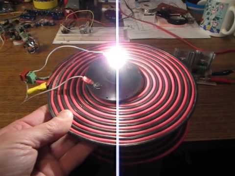
Bifilar Pancakes Inductive Coupling
Experiment with inductive coupling between single and bifilar combinations of coils.
Both bifilar coils ar connected as per Nikola Tesla patent. Both are 12ga wire and 8" outer dia. Transmitting coil being powered by ZVS circuit idling at 70mA at 12V. During this test voltage has been increased to 24VDC.
Toroid came from PSU and half of the original windings were removed. ZVS capacitor 220nF/250V, parallel capacitor for coil has been selected experimentally and it's value will depend on coil parameters. I used 14Ga household electrical wire secured with super glue.
Thanks
V
249 19

Simple Wireless Electricity System
A pancake coil and a transistor. 1x AAA battery is being used to power the circuit.
The coil is an old modem lead, with 2 wires running through it. The wires are connected following Nikola Tesla's classic pancake coil method.
All receiving coils are made from similar former computer modem leads.
The first receiving coil shown is a single winding coil, not bifilar, with an LED connected across the start and end of the wire (thanks to YalgorupIT for the middle positioning of the LED idea, he makes his like that and it's a good neat placement).
The second is a pyramid/conical type of bifilar coil, with a blocking oscillator inside and LED out of the top.
The third coil is a bifilar pancake, with a blocking oscillator circuit mounted on the top. This coil shows that the energy can power circuit loads.
The effect of transfer was discovered by accident a couple of weeks ago.
I was moving some circuits out of the way in the utility room and one pancake coil oscillator was running via a calculator solar cell. As I crossed over the top of that coil, another pancake oscillator flashed
Reducing the components to just the transistor gave this circuit shown today :)
I'm not sure of the amperage used, but is likely similar to a Joule Thief draw. A 1ohm resistor may well be used to discover the draw as experiments carry on.
No capacitors, no resistor etc, the pancake is filling in for the usual components with its own resistance and capacitance!
Commercial rights are reserved for Thortz Energy
600 20
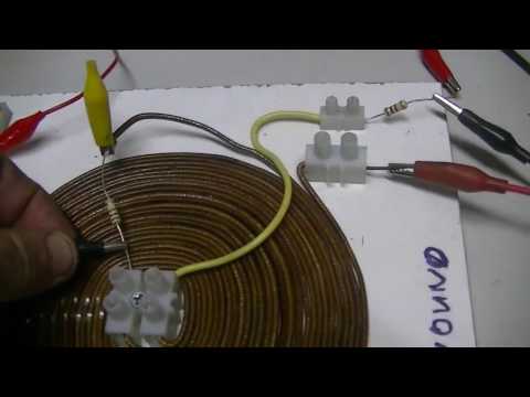
Tesla bifilar coil anomaly
From what we know, at any one point in the windings of a coil, the current flowing through the coil must be the same.
That is, until you find that it is not.
63 11
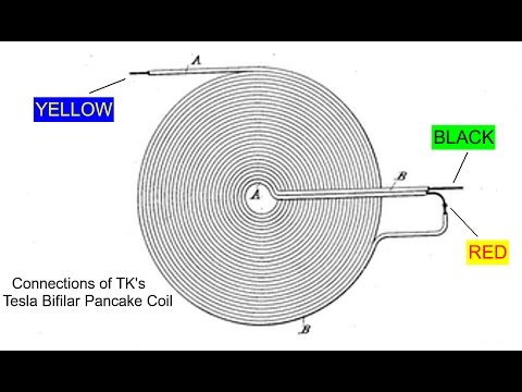
Tesla Bifilar Coil DC Resistance: Pancake (1)
Here I test the DC resistance of a Tesla Bifilar Pancake coil (Tesla's patent #512340) using the Fluke 87-III digital multimeter in its High Precision mode.
First I test the entire coil, then I test each of the two windings separately. The DC resistances of the two windings are each one-half of the total resistance of the entire coil, as expected.
Claims have been made that there is something special happening to the DC resistance of Tesla Bifilar-wound coils, whether flat or solenoidal. Specifically, that the TBF winding has half the DC resistance of a monofilar coil with the same total length of wire. At the moment I don't have a matching monofilar coil to compare, but I can do the next best thing: measuring each winding separately in this TBF coil and comparing that to the measurement of the whole coil.
I have also measured solenoidal coils where I do have TBF and monofilar windings of the same total length, and they have the same DC resistance, so at least in the coils I have tested thus far, the "half resistance" claim is not supported by my findings.
With the same wire being used, it should not matter at all whether the wire is straight, wound in a monofilar coil or a bifilar coil or even bunched up like a brillo pad; the total DC resistance should only depend on the total length of the wire.
However, it is trivially easy to mis-connect the crossover center tap when making the Tesla Bifilar winding, simply by getting the wires mixed up, so that the top of one winding is connected to the bottom of the _same_ winding. This isolates this half of the coil from the measurement and gives the false reading of half the expected total resistance in the other half of the coil. Could a mistake like this be where the "half resistance" claim comes from?
70 7

Tesla bifilar coil Overunity Effect
Power in, and dissipated power, measured in a series circuit.
We measure the total power in, by way of ohms law.
Then we measure the power dissipated by each component, in a series fashion, but ohms law seems to fail.
211 35

Power distribution in a Bifilar Pancake Coil
Website link: https://www.vorticesdynamics.org.uk
I like to demonstrate the power distribution in a bifilar pancake coil. I use two 100 Ohm resistor connected in series to the coil and connect across each resistor an LED. My statements about the current is based on the load in question and not to understand as a general assumption. Current and voltage alignment is more complicate and various with the load.
1 1

Series parallel bifilar coil resonance, creates high energy gain.
In this video the circuit is shared, that creates energy amplification from series parallel resonance in a bifilar coil. This is done by using the negative inductive spike of a bifilar coil.
The voltage is jumping to a much higher energy state!
Energy is related to voltage squared: a gain of 10V relates to a gain of 100 times more energy.
In this video the 2 coils are not magnetically coupled. This will be done in future experiments.
A link to the article about series parallel resonance: http://www.accelinstruments.com/Applications/WaveformAmp/Magnetic-Field-Generator.html
Donations are appreciated: https://PayPal.Me/masterivo
49 1
